Author Archives: admin

RaceCapture Pro

Over the winter I decided to switch from my homemade digital dashboard solution to the Autosport Labs RaceCapture Pro.

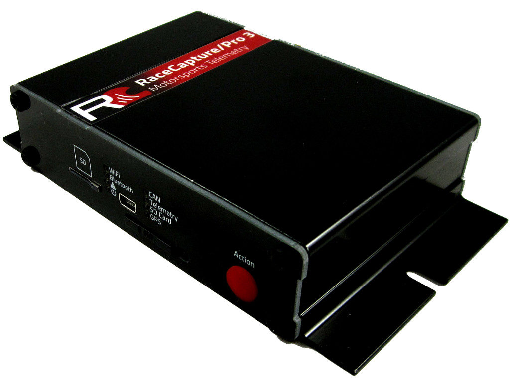
In terms of logging hardware, it includes a ton of features:

  • 8 12bit analog inputs
  • 3 digital I/O
  • 4 timer inputs
  • 10Hz GPS
  • 3-axis accelerometer
  • 2 CANBUS busses
  • RS-232
  • WiFi
  • Bluetooth
  • SD card storage

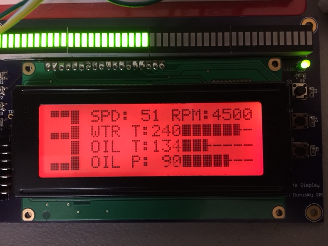
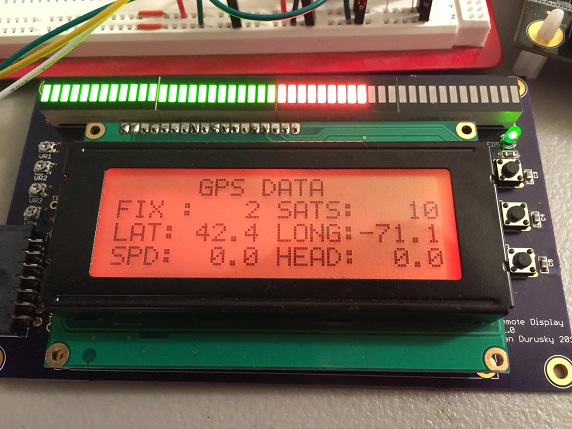
The other cool thing is that its designed for you to use a tablet as the dashboard display. The tablet connects to the main unit via bluetooth and looks something like this:

There are many configuration options and you can have as many “screens” as you want so you can cycle through different displays as needed.

In terms of software, the RaceCapture app can be run on a PC or even on the tablet itself. The idea is that after a session, you can pull out the dashboard tablet and check out the data. You can plot channels and compare laps.

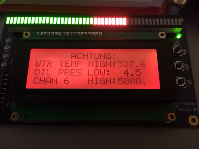
I ended up using the RaceCapture Pro mk3 connected to my water temp, oil temp, oil pressure, and TPS sensors. I used an Amazon Fire HD8 tablet as the dash as you can see here:

The RCP system uses LUA scripting to configure much of the hardware and also to allow you to write custom vitual channel scripts. Here is the LUA script i wrote to setup my hardware as well as the ShiftX2 shift light. It also calculates speed based off of the E36’s differential speed sensor and gear based on speed and RPM.

setTickRate(10) --10Hz 
-- What CAN bus ShiftX2 is connected to. 0=CAN1, 1=CAN2
sxCan = 1
-- 0=first ShiftX2 on bus, 1=second ShiftX2 (if ADR1 jumper is cut)
sxId=0
--Brightness, 0-100. 0=automatic brightness
sxBright=0
sxCanId = 0xE3600 + (256 * sxId)
println('shiftx2 base id ' ..sxCanId)
--virtual channels 
--addChannel("name",SR,prec,min,max,"unit") 
speeddiff_id = addChannel("Speed_",10,0,0,160,"MPH") 
gear_id = addChannel("Gear",5,0,0,5,"gear") 
brakeg_id = addChannel("BrakeG",10,2,0,2,"G")
--global constants 
first = 4.20 
second = 2.49 
third = 1.66 
fourth = 1.24 
fifth = 1.00 
final = 3.46 
tirediameter = 24.7 
--global variables 
rpm = 0 
rpm_diff = 0 
speed = 0 
function updateSpeedDiff() 
   rpm_diff = getTimerRpm(1) 
   speed = rpm_difftirediameter0.002975 
   speed = speed + 0.5 -- round because 0 prec. truncates 
   setChannel(speeddiff_id, speed) 
end 
function updateGear() 
   rpm = getTimerRpm(0) 
   local gearErr = 0.15 
   local gear = 0 
if speed > 2 then 
      ratio = rpm/(rpm_diff*final) 
      if ((first  - ratio)^2) < (gearErr^2) then gear = 1 end 
      if ((second - ratio)^2) < (gearErr^2) then gear = 2 end 
      if ((third  - ratio)^2) < (gearErr^2) then gear = 3 end 
      if ((fourth - ratio)^2) < (gearErr^2) then gear = 4 end 
      if ((fifth  - ratio)^2) < (gearErr^2) then gear = 5 end 
   end 
   setChannel(gear_id, gear) 
end 
function autoLog() 
   if speed > 10 and rpm > 500 then 
      startLogging() 
   end 
   if speed < 5 and rpm < 100 then 
      stopLogging() 
   end 
end 
function sxOnUpdate()
  --add your code to update ShiftX2 alerts or linear graph during run time.
  --Runs continuously based on tickRate.
--uncomment the below for Direct RPM on input 0
  sxUpdateLinearGraph(getTimerRpm(0))
--update engine temp alert
  sxUpdateAlert(0, getAnalog(0))
--update oil pressure alert
  sxUpdateAlert(1, getAnalog(2))
end
function sxOnInit()
  --config shift light
  sxCfgLinearGraph(0,0,0,7000) --left to right graph, linear style, 0 - 7000 RPM range
sxSetLinearThresh(0,0,4000,0,255,0,0) --green at 3000 RPM
  sxSetLinearThresh(1,0,5400,255,255,0,0) --yellow at 5000 RPM
  sxSetLinearThresh(2,0,6800,255,0,0,10) --red+flash at 6500 RPM
--configure first alert (right LED) as engine temperature (F)
  sxSetAlertThresh(0,0,215,255,255,0,5) --yellow warning at 215F
  sxSetAlertThresh(0,1,225,255,0,0,10) -- red flash at 225F
--configure second alert (left LED) as oil pressure (PSI)
  sxSetAlertThresh(1,0,0,255,0,0,10) --red flash below 8 psi
  sxSetAlertThresh(1,1,8,255,255,0,5) --yellow flash 8-12 PSI
  sxSetAlertThresh(1,2,12,0,0,0,0) --above 12, no alert
end
function sxOnBut(b)
  --called if the button state changes
  println('button: ' ..b)
end
---ShiftX2 functions
function sxSetLed(i,l,r,g,b,f)
  sxTx(10,{i,l,r,g,b,f})
end
function sxSetLinearThresh(id,s,th,r,g,b,f)
  sxTx(41,{id,s,spl(th),sph(th),r,g,b,f})
end
function sxSetAlertThresh(id,tid,th,r,g,b,f)
  sxTx(21,{id,tid,spl(th),sph(th),r,g,b,f})
end
function setBaseConfig(bright)
  sxTx(3,{bright})
end
function sxSetAlert(id,r,g,b,f)
  sxTx(20,{id,r,g,b,f})
end
function sxUpdateAlert(id,v)
  if v~=nil then sxTx(22,{id,spl(v),sph(v)}) end
end
function sxCfgLinearGraph(rs,ls,lr,hr) 
  sxTx(40,{rs,ls,spl(lr),sph(lr),spl(hr),sph(hr)})
end
function sxUpdateLinearGraph(v)
  if v ~= nil then sxTx(42,{spl(v),sph(v)}) end
end
function sxInit()
  println('config shiftX2')
  setBaseConfig(sxBright)
  if sxOnInit~=nil then sxOnInit() end
end
function sxChkCan()
  id,ext,data=rxCAN(sxCan,0)
  if id==sxCanId then sxInit() end
  if id==sxCanId+60 and sxOnBut~=nil then sxOnBut(data[1]) end
end
function sxProcess()
  sxChkCan()
  if sxOnUpdate~=nil then sxOnUpdate() end
end
function sxTx(offset, data)
  txCAN(sxCan, sxCanId + offset, 1, data)
  sleep(10)
end
function spl(v) return bit.band(v,0xFF) end
function sph(v) return bit.rshift(bit.band(v,0xFF00),8) end
function onTick()
  updateSpeedDiff()
  updateGear()
  autoLog()
  sxProcess()
end
sxInit()

See my latest RaceCapture LUA scripts on my Github.


Update: Digital Dashboard

I used the dashboard through the rest of 2015 and 2016 and it worked great. The hardware was solid and never skipped a beat. The display worked well and the shift light was particularly useful. I was also able to use the exported data to create track videos using RaceRender such as seen here:

However, I sort of hit a wall once the data was collected. I was able to make GPS plots and certain calculations in Excel, but besides screening for low oil pressures and high temps, it left a lot to be desired. A huge part of data analysis is using it to learn where and why you were fast or slow on a given lap. This requires much more advanced displaying and calculation of data to make it easier to pickup the clues and to develop as a driver. The problem is that all of the professional analysis software is locked to their proprietary data formats so there’s no way to use my data with their software.

This led me to eventually abandon my home-brew solution and look into the RaceCapture system from Autosport Labs. It’s a highly customizable, open source solution, that includes solid hardware PLUS pretty decent software. Their platform is growing fast and very receptive to community feedback so what’s not to like? I’ll make a another post with my latest data logging setup.


B.E.T.H. ROS

This is a quick capture of the steps i used to install ROS on a Raspberry Pi 3 and use it to control my hexapod, B.E.T.H. I’ll updated it with the bumps in the road as i hit them.

This is based off Kevin O’s hexapod ROS build which can be followed here: http://forums.trossenrobotics.com/showthread.php?6725-ROS-Hexapod-project-Golem-MX-64-4dof

Hardware

  • Raspberry Pi 3
  • USB2AX
  • Playstation 3 controller

Software

  • Ubuntu Mate 16.04
  • ROS Kinetic
  • https://github.com/KevinOchs/hexapod_ros

Step 1: Install ROS

http://wiki.ros.org/kinetic/Installation/Ubuntu

  • Boot Ubuntu Mate 16.04
  • Resize partition, reboot
  • sudo rpi-update, reboot
  • Software and Updates, allow “restricted,” “universe,” and “multiverse.”
CATKIN_IGNORE gazebo

CATKIN_IGNORE hexapod-sound

sudo apt-get install ros-kinetic-tf, and joystick, and state publisher

Step 2: Install hexapod-specific nodes using Kevin’s Github instructions

Step 3: Press the start button and you have control via the DS3.

One of my goals is to learn more about ROS by creating nodes that support additional gait types. I’ll keep you posted.

M3 Updates for Spring 2016

I’m getting really bad about documenting what i’m doing and even updating the blog. But here’s a brief recap of what went on over the winter:

  • Oiling System
  • Power Steering System
    • New reservoir and hoses. Used a custom hose for the reservoir to cooling trumpet to eliminate the weak factory crimp connection
  • New shocks/struts/springs
    • TCKline DA shocks/struts with 450/500# springs
    • I got these used for a pretty good deal and had them rebuilt
  • Front subframe reinforcements installed
  • Cooling System
    • New thermostat and housing
    • New S54 Z3M radiator
    • Spal electric fan
    • Custom ducting
  • New belt tensioner (converted to hydraulic) and belt
  • Deleted all A/C components, washer, other misc bits
  • Thinned wiring harness to remove unneeded wiring


Digital Dashboard Dissection: Temperature Sensors

This is the first of a few posts where I’ll break down a certain subsystem of the digital dashboard and explain in more detail. First up: temp sensors.

TSblockdiag

The temperature sensing subsystem consists of a few parts. First is the sensor itself. Then, the circuitry on the PCB consists of a buffer, a filter, and an ADC. Lastly, the digitized input is processed in software on the processor.

For temp sensors, I chose the AEM 30-2012 temperature sensor.

302012Physically, it is a 1/8″ NPT thread sensor and comes with the mating connector and terminals. I chose this sensor because its fairly cheap at around $40, is quite accurate (+/- 1.5C), and comes with good support and documentation from AEM.

The sensor works as a variable resistor whose resistance varies with temperature. The datasheet provides a nice table showing how the resistance changes over a broad temperature range. This table will be discussed later in the software section.

Next up is the electrical design consisting of the sense circuit, buffering, filtering, and analog-to-digital conversion.

The easiest way to convert a variable resistor to a voltage signal is to put it into a voltage divider using a pull-up resistor. In this configuration, the output voltage will vary with resistance and thus temperature. The AEM 30-2012 datasheet even providers a reference schematic:

TSdivider

This is the schematic for this part of my board. I’m using a 2.2k resistor for the pull-up (R3). I also put a jumper between the sensor input (SENS1_IN) and this pullup so that i can disable it if i’m using a sensor that provides its own voltage output.

TScircuit

Using this configuration, the voltage will scale from 0-5V according to the temperature by:

SENS1_IN = 5V * ( Rsensor/(Rsensor + Rpullup) )

tempvoltageplot

Once we have a sensor voltage signal, it’s a good idea to buffer it. A buffer provides a high impedance input that won’t load down the sensor. It also provides a low impedance output that is able to drive the next stage. Basically think of it as a divider between the outside world and your processing circuitry. The easiest way to make a buffer is to use an opamp buffer as shown below, U3A.

TScircuit

The next stage is a basic RC low pass filter using R11 and C5. These values create a low pass filter with a cut off at F = 1/(2*Pi*R*C) = 723hz. This is plenty high for most sensors (this circuit is used for all 8 input channels and is intended to be flexible), but is low enough to filter out most unwanted noise.

Next up is the ADC. For this project i chose the 8 channel, 12-bit, Microchip MCP3208. It’s SPI bus makes interfacing with the processor easy. 12 bits provides a max value of 2^12 = 4096 for a range of 0-4095. So each bit represents 5.0V/4096bits = 1.22mV/bit which is more than adequate resolution for this application.

Lastly, we have the software which processes this digital information. Because the temperature sensor is nonlinear, we have to use a lookup table to convert its output voltage (which represents its resistance which represents the temperature) to a temperature. The datasheet gives us:

TSLU

Here is the table implemented in code using the digital representation of the voltage and degrees C:


// Temp LUT - digital, degC
short tempLUT[39][39] = {
{ 325, 150 },{ 362, 145 },{ 404, 140 },{ 451, 135 },
{ 505, 130 },{ 565, 125 },{ 634, 120 },{ 710, 115 },
{ 796, 110 },{ 892, 105 },{ 1000, 100 },{ 1118, 95 },
{ 1249, 90 },{ 1391, 85 },{ 1544, 80 },{ 1708, 75 },
{ 1882, 70 },{ 2063, 65 },{ 2248, 60 },{ 2435, 55 },
{ 2621, 50 },{ 2803, 45 },{ 2976, 40 },{ 3138, 35 },
{ 3287, 30 },{ 3421, 25 },{ 3540, 20 },{ 3644, 15 },
{ 3732, 10 },{ 3807, 5 },{ 3869, 0 },{ 3920, -5 },
{ 3961, -10 },{ 3993, -15 },{ 4018, -20 },{ 4038, -25 },
{ 4053, -30 },{ 4065, -35 },{ 4074, -40 }};

The following code converts the digitized voltage input to a temperature using the lookup table. First it searches the lookup table for the closest match that less than the input value. The input value must then be between this match and the next one higher. It then linearly interpolates between these two table entries to find the equivalent temperature.


/* Temp Sensor Look Up Table
* Returns Temp in C
*/
float ToTemperature(unsigned short adcIn) {

short lowerI = 0;
short upperI = 0;
for(short i=0; i&amp;amp;lt;39; i++) {
   if(tempLUT[i][0] &amp;amp;lt;= adcIn ){
      lowerI = i;
   }
   else{
      upperI = i;
      break;
   }
}
return tempLUT[lowerI][1] + (float)( tempLUT[upperI][1] - tempLUT[lowerI][1] )*( adcIn - tempLUT[lowerI][0] )/(float)( tempLUT[upperI][0] - tempLUT[lowerI][0] );
}

And that’s about how it works, from sensor to computed value.

Digital Dashboard Installed!

It’s not super pretty, but it works!image1 (3)

Over the past few months I installed the following sensors:

  • Water Temp (AEM 30-2012) installed where the throttle body heater coolant bung used to be in the head. It threads right in with an adapter i got from TRM.
  • Oil Temp (AEM 30-2012) installed into Bimmerworld oil distribution block mounted to oil filter housing
  • Oil Pressure (AEM 30-2131) also installed into the Bimmerworld ODB.
  • Throttle Position I get by tapping into the factory sensor at the throttle body. It is a 0-5V signal.

I loomed up the wiring and ran it through the firewall behind the glove box nice and neat. Everything still looks neat and clean in the engine bay. Once through the firewall, I crimped Molex MicroFit contacts on the wires and inserted them into the connector which mates to the “Main Unit”.

The Main Unit is installed in the glove box. For the moment its just the raw PCBs mounted on stand offs screwed to the bottom of the glove box. I need to work on an enclosure for this, but for now at least its secure and neat. (I’ll add a pic of this soon).

I then made another harness with the MiniFit connector and ran it behind the dashboard to connect between the Display and the Main Unit. the Display is secured via its bottom stand-offs with velcro. Again, not pretty, but its secure enough for the time being.

Functionally, everything is working great. I’m happy with the legibility of the display. The shift light is awesome. All sensors are behaving. It’s logging data well. It’s really pretty cool!

My intention is that over the next few weeks, I’ll write posts detailing each subsystem of the device including the sensor, circuit, and software, etc. Here’s the first one:

Digital Dashboard Dissection: Temperature Sensors

The M3, rollbars, subframes, cracks…

Last fall I was prepping for the install of a bolt-in 4-point roll bar when i noticed a crack under my back seats…

IMG_1114 IMG_1113

That couldn’t be good so I had an excellent local race shop, Vintage Sports & Restoration, take a look. And they found a cracked subframe.

image2_small image1_small


This is a fairly uncommon failure on an E36. Typically it is the stubframe *mounts*, which are a part of the unibody of the car, that crack. My mounts were fine, but it was this ear of the subframe itself that cracked.

The shop also noticed that the previous owner had installed solid aluminum differential mounts, but kept the original rubber subframe mounts in place. With no isolation between the diff and the subframe, all that driveline energy was being applied to the rubber bushings. They quickly died and eventually fatigued the subframe and it cracked. At the point, the driveline energy was being coupled to the unibody asymmetrically through three instead of the four mounting points and that probably caused the stress crack under the seats. So the moral of the story is to understand how bushings/mounts work and make sure they’re being used as a system.

So VSR installed a new freshly painted subframe with 75D mounts. Being the foundation of the rear suspension, we wanted a firm interface here. We opted against going full aluminum because we do want to reduce some of the high frequency energy that can be rough on a street driven car both in sound and metal fatigue.

We then used 95A poly diff mounts so that there is some give to the driveline, but it it still much stiffer than stock to sharpen the response a bit.

If that wasn’t enough, the shop said my diff was making a lot of noise and the left side output shaft bearing was shot. That snow balled into a brand new 3.46 2-clutch, 40%, 45/45 LSD from Dan at diffsonline.com. Dan’s work is top notch and his diffs are very common among the club racers. I rebuilt the LSD in my old E30, but I decided to let the pros handle this one.  Since the car is still driven to and from tracks as far a way as 6-9 hrs, I chose the 3.46. The more racey 3.64 is perfect for a trailered race car but it revs too high for comfortable highway driving.

So as of yesterday the car is home again. Here’s a final rundown of what’s new:

  • 4-pt bolt-in roll bar with custom harness bar height (I’m tall)
  • Repaired crack under rear seats
  • Refurbished subframe w/ AKG 75D bushings
  • Rebuilt 3.46 LSD from diffsonline.com. 95A bushings

IMG_1306

Next up is:

  • Install seats (Cobra Suzukas w/ VAC hardware)
  • Install harnesses (Schroth ProFi 6-pts)
  • Install new valve cover gasket (I have quite a leak now) and spark plugs
  • Install oil temp, water temp, oil pressure sensors (for digital dashboard)
  • Break in new diff!


Digital Dashboard – Shield is up!

A few weeks ago my PCBs for the “Main Unit Shield” came in. Again, OSH Park delivered ahead of schedule and they look great.

shieldpcb


Seeing that i’m doing more and more builds with small surface mount parts, I decided to get a hot-air rework station. It turns out that Microcenter down the street carries a cheap unit so i picked one up and got to work. It was actually pretty easy to use. I slobbed solder paste over the pads, placed the part, and applied the heat. After about a minute the tiny solder balls in the paste would start to melt and cling together. The solder mask did its job, all the molten solder blobs found their homes on pads, the part self centered, and voila. It turned out great and was far more forgiving than I would have thought. (or so I thought).

This board was a bit more of a headache than the last board. When i first powered on the board, the ADCs were all over the place. I couldn’t get accurate readings, they should shift and wonder, it was a mess. The only good news was that the I2C pullups and connection out to the dashboard worked fine.

The ADC trouble boiled down to three issues. First, I specified the wrong opamp parts. I designed the ADC input opamp buffers as requiring rail-to-rail input (common mode voltage) and the parts I specified didn’t allow this. I replaced the Microchip MCP604s with TI OPA4342s.

Second, I found a short between two input channels which occurred because i had a via too close to a resistor pad. I removed the solder bridge and filed it away as a lesson learned for the next PCB i layout.

Even after doing the above two fixed, i was getting strange results. I think having the short killed an opamp, so i replaced it. Then that seemed to work, but then the ADC wasn’t reading correctly. I wasn’t sure if it was hardware or software at this point so i broke out the Saleae Logic Analyzer and verified the SPI bus communication. It all looked good. So I ordered more parts, replaced more parts. Still no luck.

Finally I realized that I might be cooking these parts with the heat gun. I had a couple spare parts so I decided to remove the bad parts with hot air, but solder the new ones in with the iron… and it worked. So I spun my wheels for a couple weeks mostly due to my own workmanship mistakes. Looking back on it, i think that rather than blasting the part with heat, i need to more closely mimic the temperature profile of a reflow oven. Ie, warm the board/part up for a few minutes first at a safe temperature, and then relatively quickly ramp up the heat to melt the solder and then drop it back down again.

But in the end, the board works.

shield

At this point this prototype hardware is pretty solid. I’ll continue to fine tune the software, but I’m mostly waiting for the M3 to thaw out so I can install the sensors and this unit in the car and do some field testing.

Digital Dashboard – Display Ideas

The dashboard/logger is starting to come together. Most of the sensor functionality I want is in place, it logs well, etc. The tricky part now is how to display all this info in a way that is useful and clear while driving the car.

One of the most import visual outputs is the shift light itself. The setup i’m using is fairly large and clear with enough length and resolution to hopefully make it clear where you are in the rev band and how its trending. I do hope that they are bright enough to see in the sunlight, but I think having it mounted in the factory dash area under the dash hood should make this ok.

The second most important indication is for the warning messages. If my oil pressure drops or I start to overheat, i want it to be very clear very quickly. As of now, if there is an alarm condition, the whole display changes to a warning message screen:

achtung“Warning”, “Achtung!”, “Danger to the Manifold”, would all be appropriate. At the same time the shift lights will all blink red. I can display up to three alarms at once should hopefully be enough, even for a German car.

Lastly, i thought it would be cool to have a large number display for the gear indicator. While i generally know what gear I’m in, i’m moving to a 3.46 rear end in the E36 this year and will be shifting more often so it may come in handy.

IMG_1211Working with an old school character display is pretty clunky, but it at least allows you to program 8 custom characters. I used five of the custom characters for the I, II, III, IIII, and IIII characters for the bar graph. I used the remaining three slots for the large number characters- basically an upper block, lower block, and full block. There are prettier 4 line characters out there, but I don’t have the memory for them with the bar graph.

The mbed microcontroller i’m using does have a built in controller for a 7″ 800×480 full color TFT display, but that’s for another day.

In addition to the main screen, I can scroll through different screens using the buttons on the right side of the display. As of now I have a screen showing the raw ADC data for the 8 analog inputs, a screen with all processed sensors, a screen with GPS status, a screen with some basic setup stuff. I’ll post more info on those when i get them sorted out.


Digital Dashboard – GPS

Another thing that i like about the EA LPC4088 board is that it has Xbee formfactor headers on it. EA also makes a GPS accessory that plugs into using the popular PA6H module so there is lots of community support out there for it.

The unit itself is pretty slick and has a 10hz update rate which is helpful for tracking high speed things like race cars. The device talks over a UART using standard NMEA protocol so there are plenty of parsing libraries out there. I literally had this running in a couple hours.

I also soldered on a UFL connector and attached an active external antenna. It has a magnet mount which will work well on the roof of the car.

gpspic

The precision shown on the display is only enough to get you in my  general metro area. The data logger logs six decimal places of info which is more meaningful for tracking a car on track.

This hasn’t yet left my house. I’m super eager to actually drive around with this and see how the data looks. I’m hoping it doesn’t require too elaborate of filtering.