Tag Archives: raspberry pi

Videos of B.E.T.H.!

I’ve been really slack about ironing out the last few bugs and taking some video of B.E.T.H. in action… But here it is! Some of the movements are a little erratic, but that’s because i’m filming with one hand while controlling the dual joystick controller with the other.

Here is a body forward kinematics demo. Here you can see that i can input body angles via the controller and the legs move as necessary to allow the body rotation without moving the feet.

Next is the tripod gait. This is a simple and fast gait in which two sets of three legs forming a triangle move alternately.

This is a wave gait. The wave gait is slow and moves only one foot at a time. The rest of the legs have to pull backwards in unison.

Finally, we have my favorite, the ripple gait. Two legs move at a time with one leg beginning to step as the other hits it’s peak height in the step. Because two legs move at once, its faster than the wave gait, but slower than the tripod.

For more info on gaits, here is a good article from Oricom Tech. My final code used here is available on my GitHub.

For more info on B.E.T.H., head back to the beginning.

Raspberry Pi Hardware Integration

A few weeks ago I got a Raspberry Pi to run in B.E.T.H. I had been running it all strewn around on the desk, but yesterday I finally got it all packed inside the chassis. Here’s a run down of what I did.

Parts:

IMG_0592

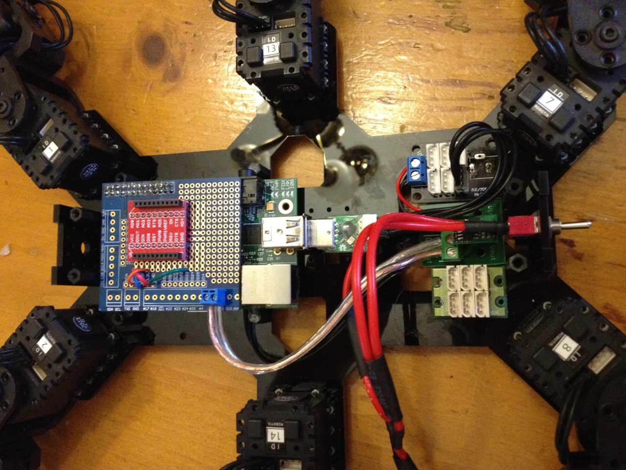
So as you can see, I mounted the Xbee breakout on the Pi Proto Plate. At first the Plate was sitting up too tall. It originally was the full length of the Raspberry Pi and spaced up enough using an extended header that it covered the ethernet and USB ports. I ended up cutting the board down and mounting it on a standard height header so it could sit lower. I mounted the Pi by glue gunning it to plastic standoffs which screw into the chassis.

IMG_0590

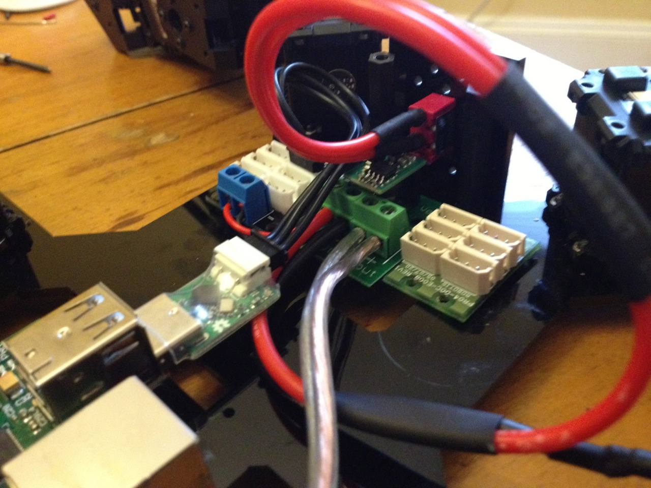
As for power, I’m running the battery power into the regulator breakout board and using it as a distribution block to jumper battery power to the power Dynamixel hub. The 5V output of the regulator goes to the Raspberry Pi. I’m powering the Pi through the GPIO power pins accessed through the Pi Proto Plate.

IMG_0594

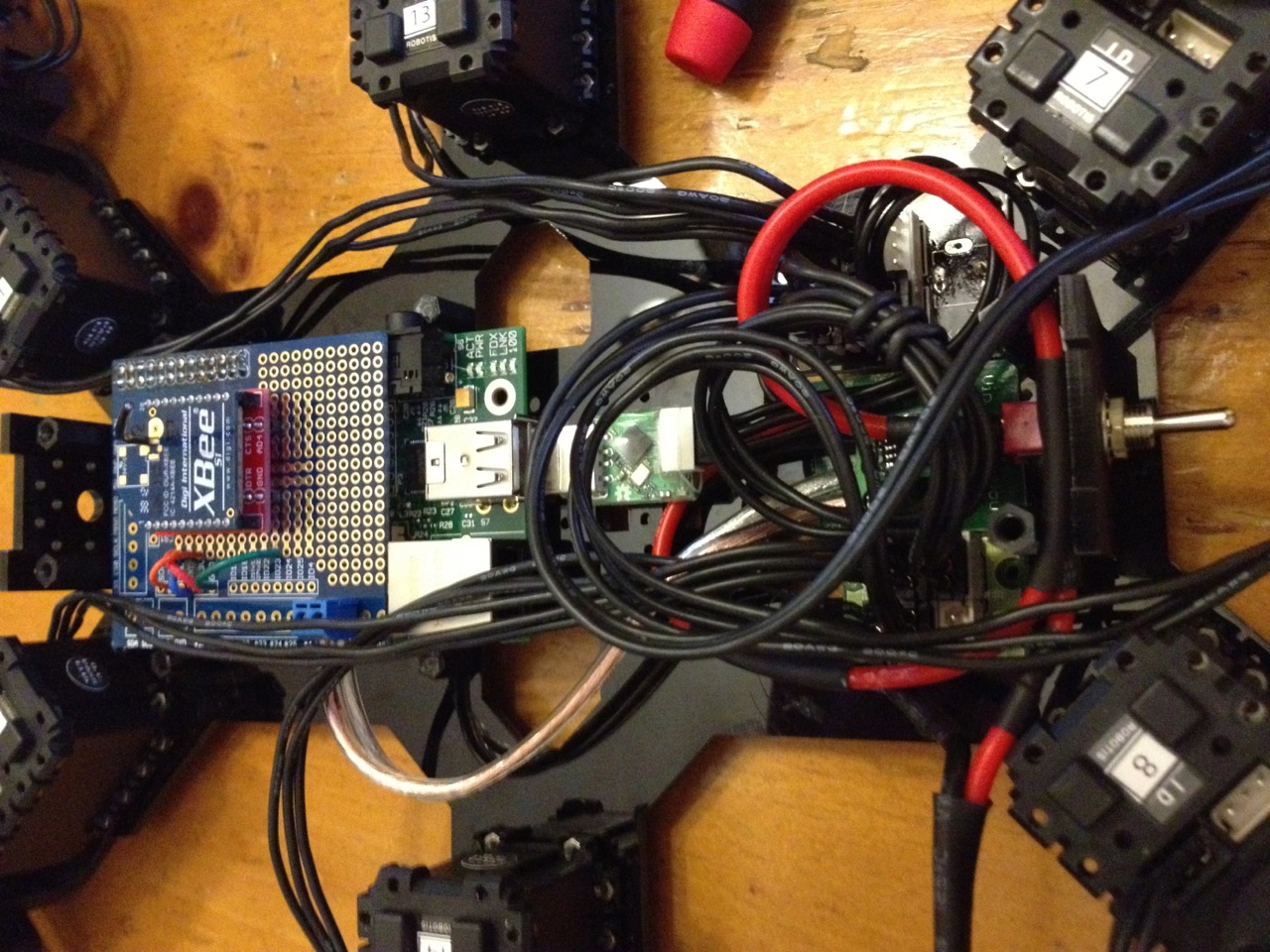
I plan to order shorter Dynamixel cables and shorten up the battery/switch wires to clean things up, but as of now it looks like this:

IMG_0598

Unfortunately the battery has to go on top of the robot. I now run the wifi adapter and USB2AX in the Pi’s USB ports. I then SSH and/or VNC in over the network to work on bot. If i have to I can reach in and plug a USB hub cable in in place of the wifi adapter.

Back to B.E.T.H.’s main index.

Phase 4: Foot Trajectory Planning and Gait Sequencing Part II

In the previous post, I went over my initial linear approach to stepping and why it didn’t work out so well. This post outlines my current method which is working much better.

The new method uses a sinusoidal “arch” shaped step in the ZX plane. This also works out well since a single sine function can cover the raise and lower part of the step in one time segment. By using a sinusoidal function for the front-to-back stepping in the X direction as well, i could cut the number of case in half to just two. The final benefit is that it produces a very smooth and natural motion with the smooth curves and foot speeds. Here’s what step code looks like:

switch (caseStep[legNum]){

                case 1: //forward raise and lower

                    leg[legNum].footPos.x = -amplitudeX*cos(M_PI*tick/numTicks);
                    leg[legNum].footPos.y = -amplitudeY*cos(M_PI*tick/numTicks);
                    leg[legNum].footPos.z = -abs(amplitudeZ)*sin(M_PI*tick/numTicks);

                    if( tick >= numTicks-1 ) caseStep[legNum] = 2;
                    break;

                case 2: // pull back

                    leg[legNum].footPos.x = amplitudeX*cos(M_PI*tick/numTicks);
                    leg[legNum].footPos.y = amplitudeY*cos(M_PI*tick/numTicks);
                    leg[legNum].footPos.z = 0;

                    if( tick >= numTicks-1 ) caseStep[legNum] = 1;
                    break;

          }// end of case statement

As you noticed, the sequencing itself is carried out by the case statement block. They key to the sequencing is in the caseStep[] array. The array has six elements, one for each leg. The variable defines at which case each leg begins. For a tripod gait, the front right leg (#1), rear right (#3), and middle left (#5) leg all start at the first case and step together. The other legs start 180deg off which is the second case. So for my prior four-case linear “triangle” step function, caseStep[] is defined as {1,3,1,3,1,3}. For the new two-case “sine” step function, caseStep[] is defined as {1,2,1,2,1,2}.

Each case statement increments caseStep[] to the next case in order to advance to the next portion of the foot step. The final code looks like:

/*************************************************
  tripodGaitSine()

**************************************************/
void tripodGaitSine(){

    float sinRotZ, cosRotZ;
    int totalX, totalY;
    float rotSpeedOffsetX[6], rotSpeedOffsetY[6];
    float amplitudeX, amplitudeY, amplitudeZ;
    int duration;
    int numTicks;
    int speedX, speedY, speedR;

    if( (abs(commanderInput.Xspeed) > 5) || (abs(commanderInput.Yspeed) > 5) || (abs(commanderInput.Rspeed) > 5 ) ){

        duration = 500;                               //duration of one step cycle (ms)
        numTicks = round(duration / SERVO_UPDATE_PERIOD / 2.0); //total ticks divided into the two cases

        speedX = 180*commanderInput.Xspeed/127;        //180mm/s top speed for 180mmm stride in one sec
        speedY = 180*commanderInput.Yspeed/127;        //180mm/s top speed
        speedR = 40*commanderInput.Rspeed/127;         //40deg/s top rotation speed

        sinRotZ = sin(radians(speedR));
        cosRotZ = cos(radians(speedR));

        for( int legNum=0; legNum<6; legNum++){                        totalX = leg[legNum].initialFootPos.x + leg[legNum].legBasePos.x;              totalY = leg[legNum].initialFootPos.y + leg[legNum].legBasePos.y;                          rotSpeedOffsetX[legNum] = totalY*sinRotZ + totalX*cosRotZ - totalX;               rotSpeedOffsetY[legNum] = totalY*cosRotZ - totalX*sinRotZ - totalY;                           if( abs(speedX + rotSpeedOffsetX[legNum]) > abs(speedY + rotSpeedOffsetY[legNum]) )
		amplitudeZ = ((speedX + rotSpeedOffsetX[legNum])*duration/3000.0);
            else
		amplitudeZ = ((speedY + rotSpeedOffsetY[legNum])*duration/3000.0);

            amplitudeX = ((speedX + rotSpeedOffsetX[legNum])*duration/2000.0);
            amplitudeY = ((speedY + rotSpeedOffsetY[legNum])*duration/2000.0);

            switch (caseStep[legNum]){

                case 1: //forward raise and lower

                    leg[legNum].footPos.x = -amplitudeX*cos(M_PI*tick/numTicks);
                    leg[legNum].footPos.y = -amplitudeY*cos(M_PI*tick/numTicks);
                    leg[legNum].footPos.z = -abs(amplitudeZ)*sin(M_PI*tick/numTicks);

                    if( tick >= numTicks-1 ) caseStep[legNum] = 2;
                    break;

                case 2: // pull back

                    leg[legNum].footPos.x = amplitudeX*cos(M_PI*tick/numTicks);
                    leg[legNum].footPos.y = amplitudeY*cos(M_PI*tick/numTicks);
                    leg[legNum].footPos.z = 0;

                    if( tick >= numTicks-1 ) caseStep[legNum] = 1;
                    break;

          }// end of case statement

        }// end of loop over legs
        if (tick < numTicks-1) tick++;
        else tick = 0;

    }//end if joystick active

}

I think it needs a little fine tuning of the speeds and step durations, but its essentially done. B.E.T.H. is now fully mobile!

Check out where this all began.
Phase 4: Foot Trajectory Planning and Gait Sequencing Part I

Thanks to my handy IK engine, I no longer need to think in terms of joint angles. All i need to do is move the tip of the foot around in 3D space using the footPos.x, footPos.y, and footPos.z variables.   Stepping is really as simple as looping and incrementing them in such a way to produce the desired movement. Incrementing X moves the foot in the forward X direction. Incrementing X and Y at the same time moves the foot on that diagonal, etc.

I’ve been putting this post off for awhile because I keep changing how I’m implementing the foot stepping. I’ll go through the history for learning’s sake.

At first I was using linear equations to “draw” straight lines with the foot. A foot would step diagonally up and forward, down and forward, then pull back along the ground in the shape of a triangle.


            switch (caseStep[legNum]){

                case 1: //forward raise

                    leg[legNum].footPos.x = ((long)(speedX + strideRotOffsetX[legNum])*tick*SERVO_UPDATE_PERIOD)/duration - (speedX + strideRotOffsetX[legNum])/4;
                    leg[legNum].footPos.y = ((long)(speedY + strideRotOffsetY[legNum])*tick*SERVO_UPDATE_PERIOD)/duration - (speedY + strideRotOffsetY[legNum])/4;
                    leg[legNum].footPos.z = ((long)height*tick*SERVO_UPDATE_PERIOD)/(duration/4);

                    if( tick >= numTicks-1 ) caseStep[legNum] = 2;
                    break;

                case 2: // forward lower

                    leg[legNum].footPos.x = ((long)(speedX + strideRotOffsetX[legNum])*tick*SERVO_UPDATE_PERIOD)/duration;
                    leg[legNum].footPos.y = ((long)(speedY + strideRotOffsetY[legNum])*tick*SERVO_UPDATE_PERIOD)/duration;
                    leg[legNum].footPos.z = height - ((long)height*tick*SERVO_UPDATE_PERIOD)/(duration/4);

                    if( tick >= numTicks-1 ) caseStep[legNum] = 3;
                    break;

                case 3: // down pull back

                    leg[legNum].footPos.x = -((long)(speedX + strideRotOffsetX[legNum])*tick*SERVO_UPDATE_PERIOD)/duration + (speedX + strideRotOffsetX[legNum])/4;
                    leg[legNum].footPos.y = -((long)(speedY + strideRotOffsetY[legNum])*tick*SERVO_UPDATE_PERIOD)/duration + (speedY + strideRotOffsetY[legNum])/4;
                    leg[legNum].footPos.z = 0;

                    if( tick >= numTicks-1 ) caseStep[legNum] = 4;
                    break;

                case 4: // down pull back

                    leg[legNum].footPos.x = -((long)(speedX + strideRotOffsetX[legNum])*tick*SERVO_UPDATE_PERIOD)/duration;
                    leg[legNum].footPos.y = -((long)(speedY + strideRotOffsetY[legNum])*tick*SERVO_UPDATE_PERIOD)/duration;
                    leg[legNum].footPos.z = 0;

                    if( tick >= numTicks-1 ) caseStep[legNum] = 1;
                    break;

          }// end of case statement

This worked well and was fast to process on the Arduino, but it had a couple of issues. First, the leg movement looked a little rigid and unnatural. Sort of jerky with the sudden direction changes. Second and most importantly, the robot wasn’t walking smoothly forward. It would sort of stutter as it moved continuously in a direction. I realized that this was because the foot was coming down and hitting the ground in the opposite direction to travel. This caused a momentary halt in the forward momentum before the foot began to pull backwards. The foot should at least be coming straight down toward the ground before pulling back. I’ll explain how I do this once its ready for prime time.

To be continued in Part II!

Jump back to the beginning of Project B.E.T.H.

B.E.T.H.’s New Brain: Raspberry Pi

Half out of future necessity and half out of simply the urge to tinker with something new, I got a Raspberry Pi. I had considered other microcomputers like the Beagle Bone Black, but I decided to go with the Pi because of software/driver maturity and large community. All the peripheral support, drivers, dev tools, etc I’d need for my projects on the Pi has been well sorted out, optimized, and nicely documented. I want to make cool stuff, not be a pioneer of the embedded linux world.

I have a couple of projects in mind for the Pi. The first will be to power my hexapod robot, B.E.T.H. The Pi will have enough grunt to run all my IK and future terrain adaption algorithms as well as do some light machine vision. The second project I think will be a digital dashboard/data logger for my car.

So far i have the Pi up and running pretty well. I’m using the WiringPi libraries to recreate some of the Arduino functions. It was fairly straight forward porting over the original arduino code to C++ on the Pi. I’ve been coding on the Pi directly using the Geany IDE in X. I’m using floating point math to improve accuracy where ever effective.

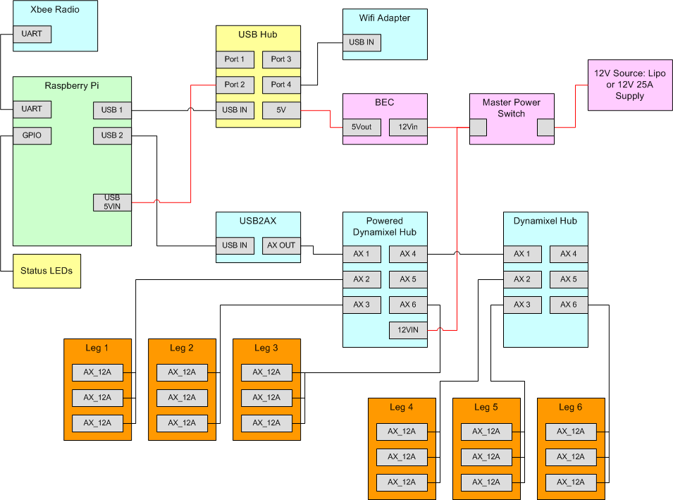
The overall hardware plan for B.E.T.H. looks like this:

hex

I’m using an Xbee breakout board from Sparkfun to physically connect the Xbee. It only takes power, ground, TX, and RX connected to the Pi’s UART and it works like a champ. Note that the Pi’s UART is configured to run a console output by defualt. You have to disable that functionality before its free to use.

To control the Dynamixel AX-12A servos, I’m using the USB2AX from Xevelabs. Its great due to its small form factor and USB speed optimizations. For software, you use the Robotis Dynamixel SDK.

The BEC is an RC type from Castle Creations. It works perfectly because its small and light, can take up to 25VDC in, and the adjustable output is programmed to 5.1V by default which is perfect for powering the USB hub and Pi. UPDATE: The CC BEC crapped out on me after about 20 minutes. I’m not sure why. I’ve since switched to the Murata switching regulator and it’s been great.

The D-Link DWA-131 USB wifi adapter isn’t necessary for running B.E.T.H., but its needed to SSH/VNC into the Pi or to run the Pi directly and access the network/internet wirelessly. For $20 its worth having. I chose this model because the chipset is supported out of the box by the linux kernel and again, its pretty small.

The last part I needed was a powered Dynamixel hub. This acts as a normal Dynamixel hub but it also provides an easy interface for applying power to the servos. I’ll probably use the set screw terminals as a distribution block for branching power.

My next task is cramming all of this stuff into the hex body!